Home › Trains › Jupiter › Explorer
Jupiter, inside and out
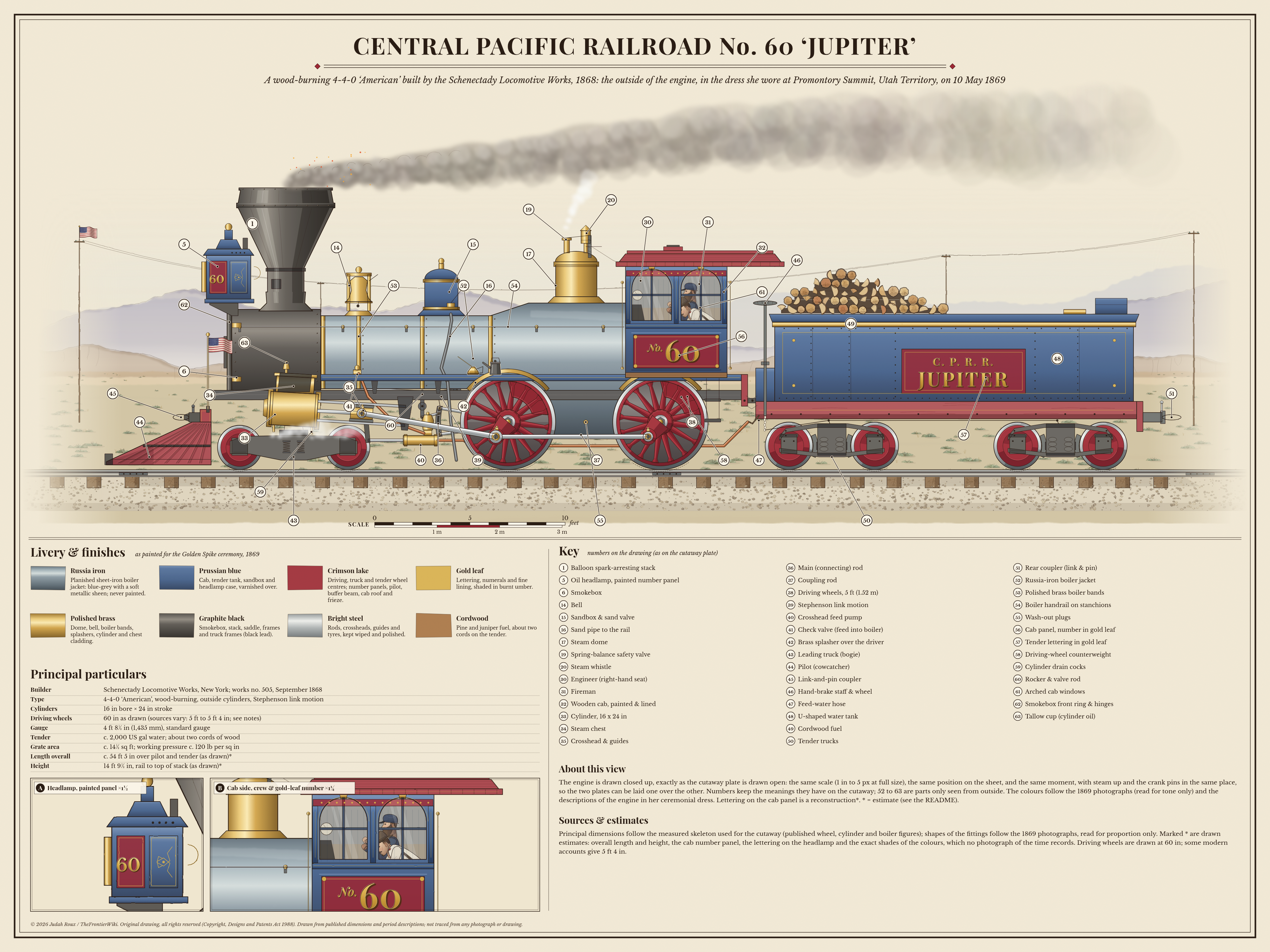
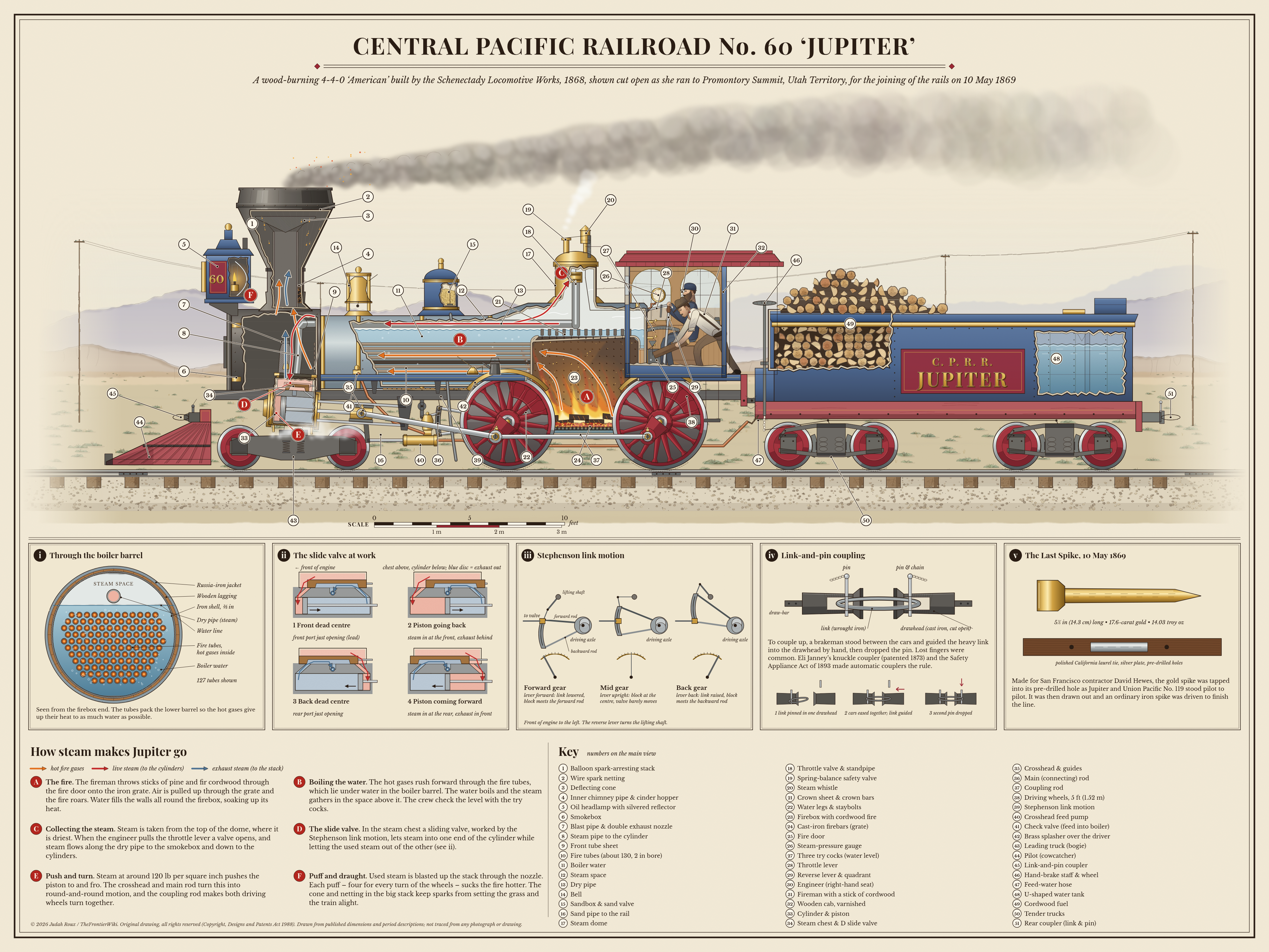
Central Pacific No. 60 Jupiter was a wood-burning 4-4-0 built by the Schenectady Locomotive Works in 1868. On 10 May 1869 she stood pilot to pilot with Union Pacific No. 119 at Promontory Summit, Utah Territory, when the rails were joined. Tap or point at a number to see what each part does, peel the engine open to watch the fire and steam at work, or take the six-step tour.


Step 1 of 6
The fire
All the numbered parts (72)
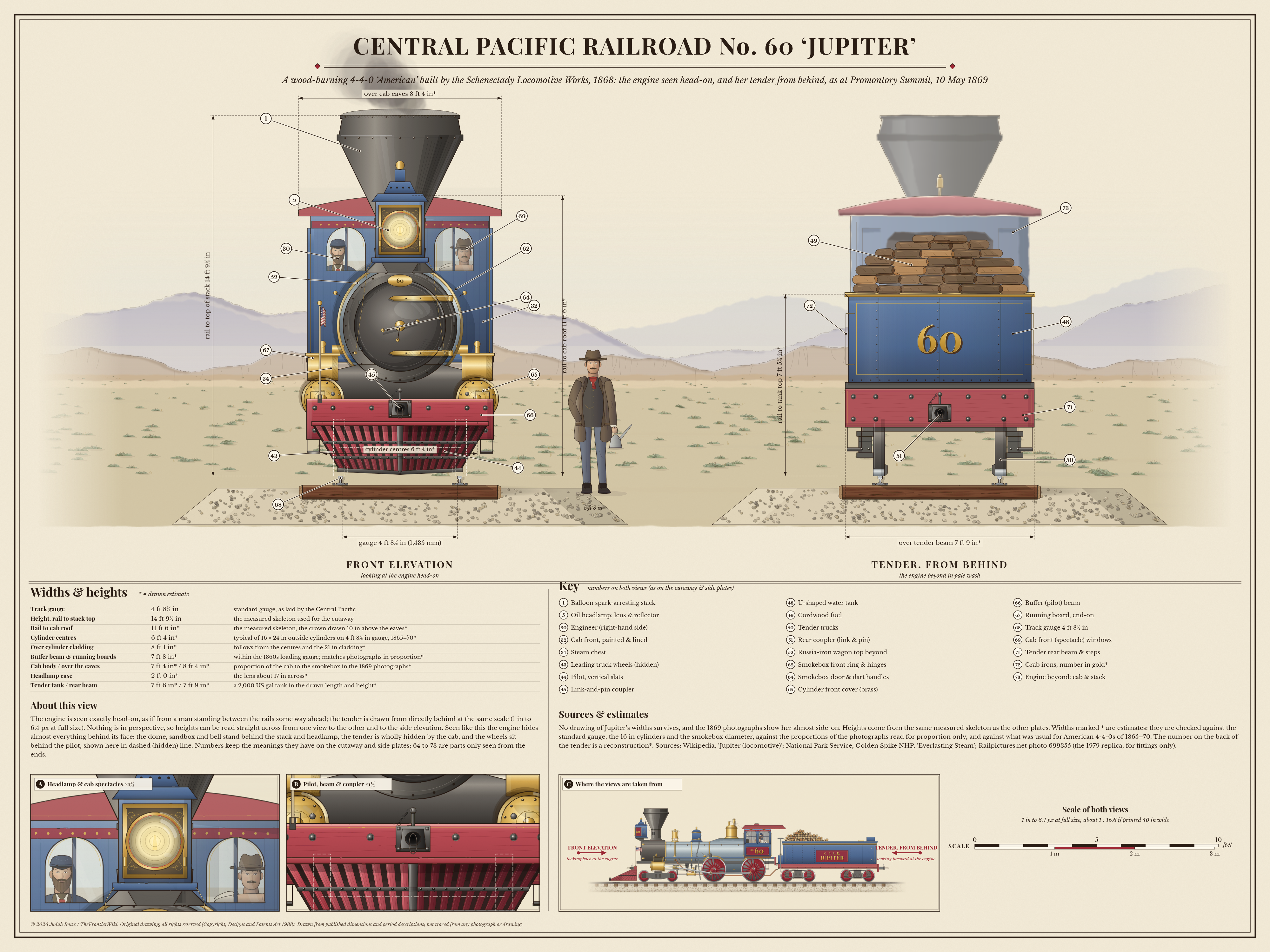
A number means the same part on every view. Numbers 52–63 are only seen from outside, and 64–73 only from the ends (70 is not used). * = drawn estimate or reconstruction.
- 1 Balloon spark-arresting stack Boiler & fire The big funnel-shaped chimney. Inside, a cone and wire netting stop sparks from the wood fire setting the grass and the train alight. Seen in: Outside, Cutaway, Front
- 2 Wire spark netting Boiler & fire A wire screen inside the stack. Smoke can get through, but burning sparks are caught before they fly out. Seen in: Cutaway
- 3 Deflecting cone Boiler & fire An upside-down cone inside the stack. The puffs of smoke hit it and are thrown sideways, so the sparks slow down. Seen in: Cutaway
- 4 Inner chimney pipe & cinder hopper Boiler & fire The straight pipe up the middle of the stack carries the smoke and the puffs. Cinders that drop back collect in the hopper. Seen in: Cutaway
- 5 Oil headlamp with silvered reflector* Fittings A big box lamp that burns oil. A silvered reflector behind the flame throws the light down the track. Seen in: Outside, Cutaway, Front
- 6 Smokebox Boiler & fire The black drum at the front of the boiler. Hot gases from the fire tubes arrive here, then go up the stack. Seen in: Outside, Cutaway
- 7 Blast pipe & double exhaust nozzle Steam & cylinders Used steam from the cylinders is blasted up the stack through this nozzle. Each puff sucks the fire hotter. Seen in: Cutaway
- 8 Steam pipe to the cylinder Steam & cylinders Carries live steam from the smokebox down to the steam chest, ready to push the piston. Seen in: Cutaway
- 9 Front tube sheet Boiler & fire The plate at the front end of the boiler barrel. The fire tubes are fixed into it, and the hot gases pass through into the smokebox. Seen in: Cutaway
- 10 Fire tubes (about 130, 2 in bore)* Boiler & fire Iron tubes that run through the water in the boiler. The hot gases rush forward inside them and boil the water. Seen in: Cutaway
- 11 Boiler water Boiler & fire Most of the boiler barrel is full of water. It covers the fire tubes and soaks up their heat until it boils. Seen in: Cutaway
- 12 Steam space Boiler & fire As the water boils, the steam gathers in the space above it, ready to be used. Seen in: Cutaway
- 13 Dry pipe Steam & cylinders When the throttle is open, steam flows along this pipe from the dome to the smokebox and on to the cylinders. Seen in: Cutaway
- 14 Bell Fittings A polished brass bell on top of the boiler, rung as a warning that the engine is about to move. Seen in: Outside, Cutaway
- 15 Sandbox & sand valve Fittings A box of dry sand on top of the boiler, painted Prussian blue. Opening the valve lets sand run down to the rails. Seen in: Outside, Cutaway
- 16 Sand pipe to the rail Fittings Carries sand from the sandbox down to the rail just in front of the driving wheels, to help them grip. Seen in: Outside, Cutaway
- 17 Steam dome Steam & cylinders The tall polished brass dome. Steam is taken from the top of it, where it is driest. Seen in: Outside, Cutaway
- 18 Throttle valve & standpipe* Steam & cylinders A valve on top of a pipe inside the dome. When the engineer pulls the throttle lever, it opens and lets steam into the dry pipe. Seen in: Cutaway
- 19 Spring-balance safety valve* Boiler & fire If the steam pressure gets too high, this valve lifts and lets steam blow off, so the boiler stays safe. Seen in: Outside, Cutaway
- 20 Steam whistle Fittings Steam blown through this brass whistle makes the engine's shriek, used for signals and warnings. Seen in: Outside, Cutaway
- 21 Crown sheet & crown bars Boiler & fire The flat roof of the firebox, with the fire below and water above. Iron bars across the top help it hold its shape. Seen in: Cutaway
- 22 Water legs & staybolts Boiler & fire Water fills the walls all round the firebox, soaking up its heat. Staybolts tie the inner and outer walls together. Seen in: Cutaway
- 23 Firebox with cordwood fire Boiler & fire Where the wood fire burns, right inside the boiler. Air is pulled up through the grate and the fire roars. Seen in: Cutaway
- 24 Cast-iron firebars (grate)* Boiler & fire The iron grate the fire sits on, about 14½ sq ft in area. Air comes up between the bars to feed the flames. Seen in: Cutaway
- 25 Fire door Boiler & fire The fireman throws sticks of cordwood through this door onto the grate. It is drawn wide open so you can see in. Seen in: Cutaway
- 26 Steam-pressure gauge* Cab A dial in the cab that shows how hard the steam is pushing: around 120 lb per square inch. Seen in: Cutaway
- 27 Three try cocks (water level) Cab Three small taps on the back of the boiler. The crew open them to see whether water or steam comes out, and so check the water level. Seen in: Cutaway
- 28 Throttle lever Cab The engineer pulls this lever to open the throttle valve in the dome and send steam to the cylinders. Seen in: Cutaway
- 29 Reverse lever & quadrant Cab This tall lever sets the link motion for forward, backward or in between. The notched quadrant holds it in place. Seen in: Cutaway
- 30 Engineer Cab The engineer drives from the right-hand side of the cab, working the throttle and the reverse lever. Seen in: Outside, Cutaway, Front
- 31 Fireman Cab The fireman works on the left-hand side, feeding the fire with sticks of cordwood through the fire door. Seen in: Outside, Cutaway
- 32 Wooden cab Cab The crew's wooden shelter, painted Prussian blue and varnished, with a crimson roof and fine gold lining. Seen in: Outside, Cutaway, Front
- 33 Cylinder & piston Steam & cylinders Steam pushes the piston to and fro inside the cylinder. It is 16 in across and the piston travels 24 in. Seen in: Outside, Cutaway
- 34 Steam chest & D slide valve Steam & cylinders A box on top of the cylinder. A sliding valve inside lets steam into one end of the cylinder and used steam out of the other. Seen in: Outside, Cutaway, Front
- 35 Crosshead & guides Running gear The crosshead slides along the guides on the end of the piston rod, and passes the piston's push on to the main rod. Seen in: Outside, Cutaway
- 36 Main (connecting) rod Running gear Links the crosshead to the driving wheel, turning the to-and-fro push into round-and-round motion. Seen in: Outside, Cutaway
- 37 Coupling rod Running gear Joins the two driving wheels on each side, so they both turn together. Seen in: Outside, Cutaway
- 38 Driving wheels, 5 ft (1.52 m)* Running gear The four big crimson wheels that the steam drives round. The builder's order gives them as 5 ft across. Seen in: Outside, Cutaway
- 39 Stephenson link motion* Running gear Rods and a curved link, driven from the axle, that move the slide valve. Moving the link makes the engine go forward or back. Seen in: Outside, Cutaway
- 40 Crosshead feed pump* Boiler & fire A pump worked by the crosshead as it slides to and fro. It pushes water from the tender into the boiler. Seen in: Outside, Cutaway
- 41 Check valve (feed into boiler) Boiler & fire A one-way valve where the feed water enters the boiler. Water can go in, but nothing can come back out. Seen in: Outside, Cutaway
- 42 Brass splasher over the driver Fittings A polished brass cover arching over the top of a driving wheel. Seen in: Outside, Cutaway
- 43 Leading truck (bogie) Running gear Four small wheels on a frame under the front of the engine that helps lead it round curves. Seen in: Outside, Cutaway, Front
- 44 Pilot (cowcatcher) Fittings The slatted crimson frame at the very front, built to push anything on the line out of the way. Seen in: Outside, Cutaway, Front
- 45 Link-and-pin coupler Brakes & couplings An iron link held in place by a pin. A brakeman had to guide the link in by hand, and lost fingers were common. Seen in: Outside, Cutaway, Front
- 46 Hand-brake staff & wheel Brakes & couplings Jupiter had no air brakes. The crew turned wheels like this one to put the brakes on by hand. Seen in: Outside, Cutaway
- 47 Feed-water hose Tender A flexible hose between the tender and the engine that carries water to the feed pump. Seen in: Outside, Cutaway
- 48 U-shaped water tank* Tender The tender's water tank is shaped like a letter U and holds about 2,000 US gallons. Seen in: Outside, Cutaway, Front
- 49 Cordwood fuel Tender Jupiter burned wood, not coal. About two cords of split logs were stacked in the middle of the tender. Seen in: Outside, Cutaway, Front
- 50 Tender trucks Tender Two sets of four wheels that carry the heavy tender. Their wheel centres are painted crimson. Seen in: Outside, Cutaway, Front
- 51 Rear coupler (link & pin) Brakes & couplings A link-and-pin coupler at the back of the tender, for joining on the train. Seen in: Outside, Cutaway, Front
- 52 Russia-iron boiler jacket Boiler & fire The outer skin of the boiler, made of planished sheet iron. It has a blue-grey metallic sheen and was never painted. Seen in: Outside, Front
- 53 Polished brass boiler bands Fittings Bright brass bands wrapped round the boiler jacket, kept polished for the engine's best dress. Seen in: Outside
- 54 Boiler handrail on stanchions Fittings A handrail along the side of the boiler, held up on little posts called stanchions. Seen in: Outside
- 55 Wash-out plugs Boiler & fire Screwed plugs that can be taken out so the inside of the boiler can be washed clean. Seen in: Outside
- 56 Cab panel, number in gold leaf* Cab A crimson panel on the cab side with 'No. 60' in gold leaf, shaded in burnt umber. Seen in: Outside
- 57 Tender lettering in gold leaf Tender Small 'C.P.R.R.' above a big 'JUPITER', in gold leaf on the blue tender. Seen in: Outside
- 58 Driving-wheel counterweight Running gear A heavy block in the wheel, opposite the crank pin, that balances the weight of the rods. Seen in: Outside
- 59 Cylinder drain cocks Steam & cylinders Small taps under the cylinder, opened to let water out of it. Seen in: Outside
- 60 Rocker & valve rod Running gear These pass the movement of the link motion on to the slide valve. The rest of the valve gear is hidden from outside. Seen in: Outside
- 61 Arched cab windows Cab Round-topped windows in the sides of the wooden cab. Seen in: Outside
- 62 Smokebox front ring & hinges Boiler & fire The ring round the front of the smokebox that carries the door and its hinge straps. Seen in: Outside, Front
- 63 Tallow cup (cylinder oil) Steam & cylinders A small cup that feeds tallow to the cylinder to keep the moving parts inside slippery. Seen in: Outside
- 64 Smokebox door & dart handles* Boiler & fire The round front door of the smokebox. The dart has two handles: one locks it and one tightens it shut. Seen in: Front
- 65 Cylinder front cover (brass)* Steam & cylinders The polished brass cover on the front of each cylinder. The two cylinders are about 6 ft 4 in apart, centre to centre. Seen in: Front
- 66 Buffer (pilot) beam* Brakes & couplings The crimson beam across the front of the engine that carries the coupler. It is about 7 ft 8 in wide. Seen in: Front
- 67 Running board, end-on* Fittings The walkway along each side of the engine, seen end-on. Seen in: Front
- 68 Track gauge 4 ft 8½ in Running gear The rails are 4 ft 8½ in (1,435 mm) apart: standard gauge, as laid by the Central Pacific. Seen in: Front
- 69 Cab front (spectacle) windows Cab Two windows in the front of the cab. The engineer looks out of the left-hand one as you face the engine. Seen in: Front
- 71 Tender rear beam & steps* Tender The beam across the back of the tender, with steps for climbing up. It is about 7 ft 9 in wide. Seen in: Front
- 72 Grab irons, number in gold* Tender Iron handholds on the back of the tender, and the number 60 in gold. Seen in: Front
- 73 Engine beyond: cab & stack Tender Seen from behind the tender, the engine's cab and stack show beyond it, drawn in a pale wash. Seen in: Front
The full plates
The complete printed plates, with their keys, notes, scale bars and detail drawings. The PNGs are the masters for print; the SVGs need the fonts Playfair Display and Libre Baskerville.
| Plate | Web | Vector | |
|---|---|---|---|
| Outside (side elevation) | PNG, 4000 × 3000 10.6 MB | JPEG, 4000 × 3000 1.5 MB | SVG master 2.3 MB |
| Cutaway | PNG, 4000 × 3000 10.8 MB | JPEG, 4000 × 3000 1.8 MB | SVG master 2.9 MB |
| Front & back | PNG, 4000 × 3000 10.7 MB | JPEG, 4000 × 3000 1.4 MB | SVG master 3.7 MB |